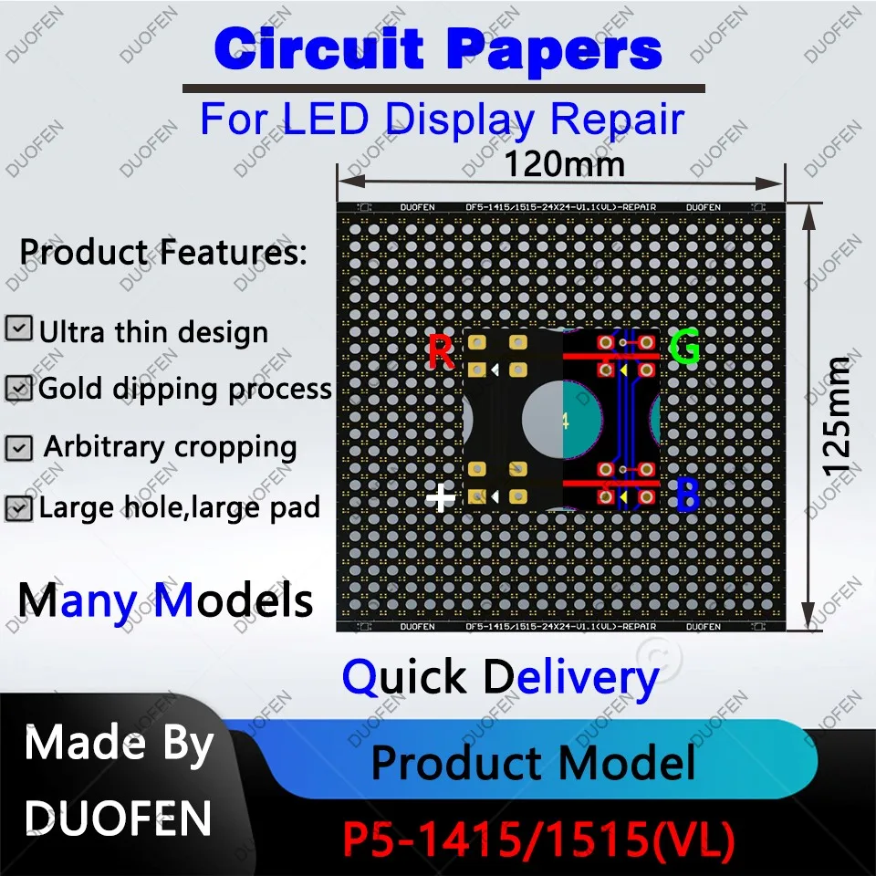
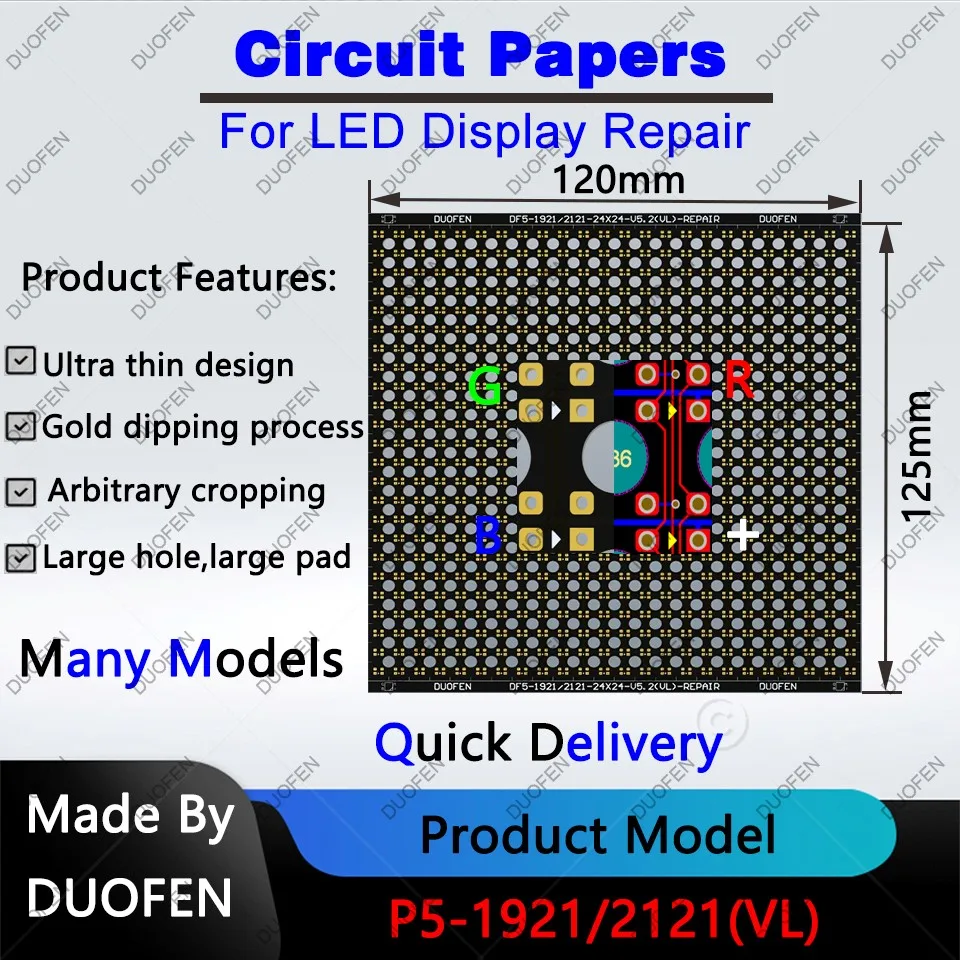
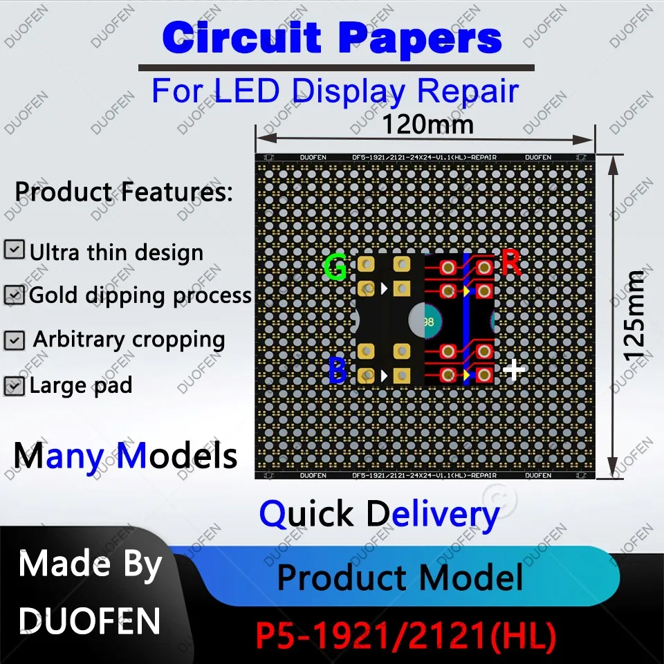
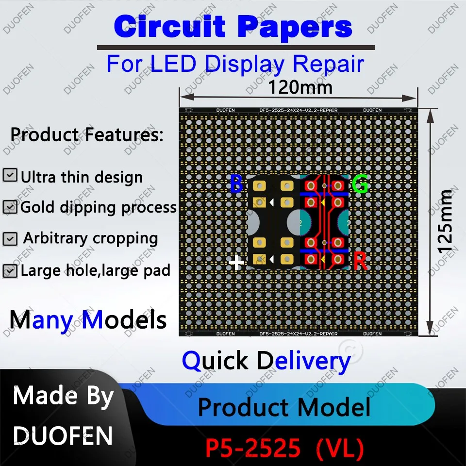
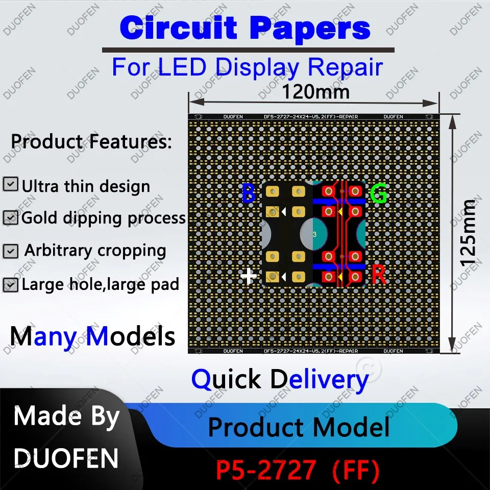
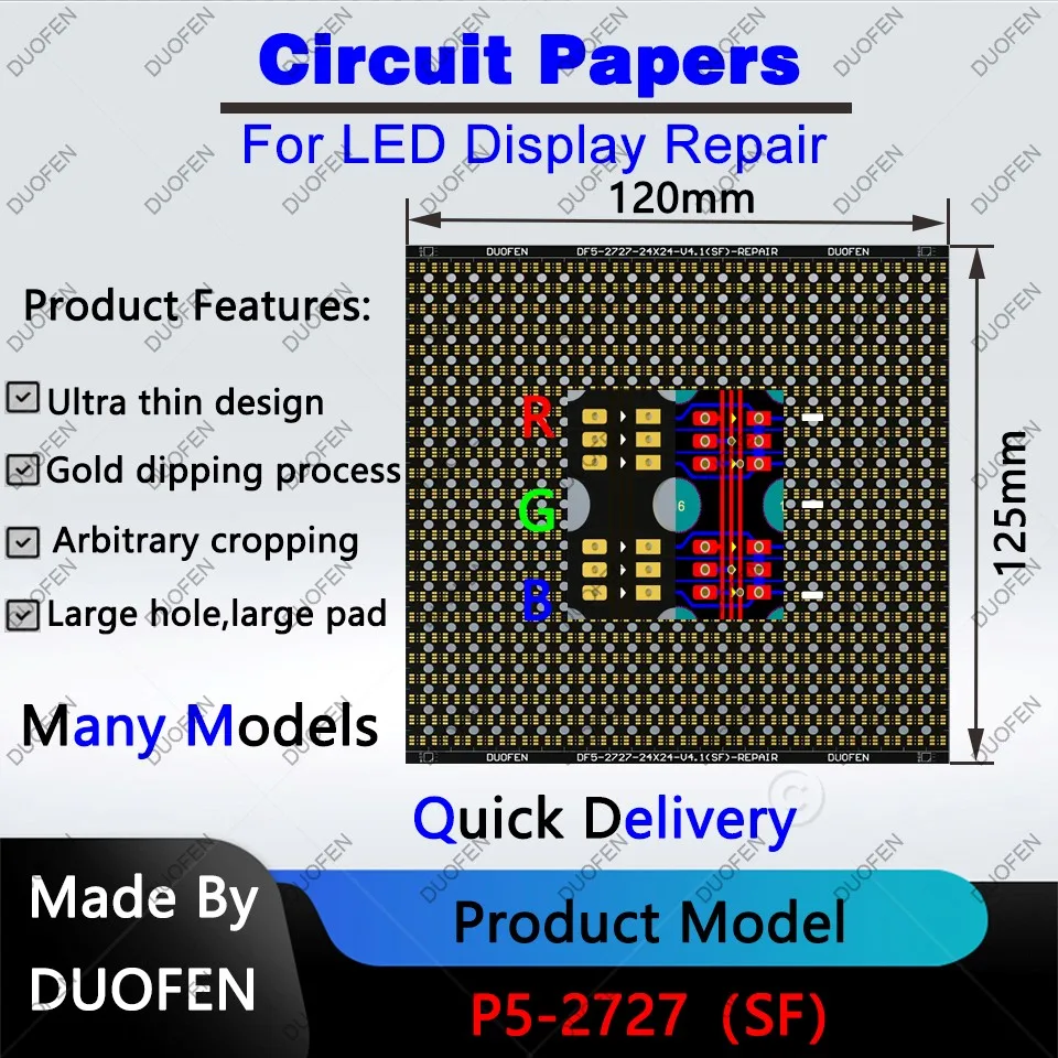
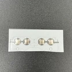
🛡️ P5 Series Circuit Paper is an innovative solution designed for the effective repair of damaged PCB pads, particularly in LED modules. This double-sided circuit paper features large holes and provides fully covered solder pads, ensuring a reliable and durable connection for your electronic applications.
1. Choosing the Right Circuit Paper
When selecting circuit paper, it's essential to ensure compatibility with your LED module. Consider the following:
- Pixel Pitch: Ensure that the pixel pitch of the original LED module matches that of the circuit paper.
- LED Bead Specifications: The specifications of the original LED beads must align with those of the circuit paper.
- Vertical vs. Horizontal Lamps: Be aware of orientation differences. Vertical lamps are more common, whereas horizontal lamps are less so. Ensure you select circuit paper appropriate for the type of lamp your original LED module utilizes.
💍 2. Measuring Pixel Pitch
To accurately determine the pixel pitch of your LED module, follow these steps:
- Use a caliper to measure the horizontal dimension (W) of the LED module.
- Count the number (N) of LED lamp beads positioned horizontally.
- Calculate the pixel pitch using the formula: Pixel Pitch (P) = Module Size (W) / Number of Lamp Beads (N). Precision in measurement is crucial, so ensure numerical accuracy is to three decimal places.
🛠️ 3. Measuring LED Bead Specifications
To measure LED bead specifications:
- Use a caliper to measure the horizontal dimension (X) of the LED beads.
- Measure the vertical dimension (Y) of the LED beads using the caliper.
- Determine the specification by calculating: LED Bead Specification = SMD (X)(Y).
4. Understanding Circuit Paper
🪶 Circuit Paper is a flexible double-layer circuit board with a thickness ranging from just 0.08 to 0.1 mm. Its thin profile allows for easy integration into various electronic applications.
5. Composition of Circuit Paper
💍 This circuit paper is composed of multiple layers, including screen printing, base materials, solder pads, holes, wiring, and cutting lines, which work together to create a reliable platform for electronic repairs.
6. Applications of Circuit Paper
⚡ During the installation, disassembly, or transportation of LED displays, collisions can lead to the detachment of PCB pads. In such instances, Circuit Paper serves as a vital resource for effective repair and restoration of functionality.
7. Using the Circuit Paper
To utilize the Circuit Paper effectively for repairs, follow these steps:
- Prepare necessary tools and consumables: anti-static bracelet, soldering iron, hot air gun, multimeter, tweezers, tin wire, solder paste, scissors, screwdriver, lamp beads, IC, and the Circuit Paper.
- Clean the damaged PCB pad. Carefully scrape away the damaged section and wipe with alcohol to prevent short circuits when applying the Circuit Paper.
- Cut the Circuit Paper into appropriate sizes and tin both sides of the pad to avoid excess solder.
- Set the soldering iron temperature to around 320°C. Using tweezers, hold the tin-coated Circuit Paper and align it with the PCB pad. Gently press it onto the pad and heat it with the soldering iron or hot air gun to ensure a strong bond.
- Once the module is connected, test functionality by lighting it up with a full white display. Adjust the brightness as needed, soldering the qualified LED beads to the Circuit Paper while verifying their orientation with a multimeter.
- If repairs are successful, apply glue to the lamp beads in the repaired area (note: glue is not necessary for indoor modules).